贾进
1
1、spi2 DMA配置如下:
#define SPI2_DMA_RX_IRQHandler DMAC1_CH5_IRQHandler
#define SPI2_RX_DMA_IRQ_PRIO 0
#define SPI2_RX_DMA_INSTANCE DMA1_Channel5
#define SPI2_RX_DMA_IRQ DMAC1_CH5_IRQn
#define SPI2_DMA_TX_IRQHandler DMAC1_CH8_IRQHandler
#define SPI2_TX_DMA_IRQ_PRIO 0
#define SPI2_TX_DMA_INSTANCE DMA1_Channel8
#define SPI2_TX_DMA_IRQ DMAC1_CH8_IRQn
2、软件开机配置:
rt_device_t spi_bus = rt_device_find(SPI_BUS_NAME);

if (spi_bus)

{

    rt_device_open(spi_bus, RT_DEVICE_FLAG_RDWR);

    LOG_D("Find spi bus %s:%x\\n", SPI_BUS_NAME, spi_bus);

    spi_dev_handle = (struct rt_spi_device \*)rt_device_find(ADC_DEVICE_NAME);

    if (spi_dev_handle == NULL)

    {

        rst = rt_hw_spi_device_attach(SPI_BUS_NAME, ADC_DEVICE_NAME);

        spi_dev_handle = (struct rt_spi_device \*)rt_device_find(ADC_DEVICE_NAME);

        if (spi_dev_handle == NULL)

        {

            LOG_E("Register spi_dev spi device fail\\n");

            return -RT_ERROR;

        }

    }

    rst = rt_device_open((rt_device_t)(spi_dev_handle), RT_DEVICE_FLAG_RDWR|RT_DEVICE_FLAG_DMA_RX|RT_DEVICE_FLAG_DMA_TX); //RT_DEVICE_FLAG_INT_RX  RT_DEVICE_FLAG_DMA_RX


    spi_dev_cfg.data_width = 16; //bit

    spi_dev_cfg.max_hz = ADC_SAMPLE_SPEED; // hz

    spi_dev_cfg.mode = RT_SPI_MODE_3 | RT_SPI_MSB | RT_SPI_MASTER;

    spi_dev_cfg.frameMode = RT_SPI_TI;//RT_SPI_MOTO; //RT_SPI_TI;

    rst = rt_spi_configure(spi_dev_handle, &spi_dev_cfg);

    LOG_D("rt_spi_configure result:%d", rst);

}
3、读取数据:
rt_spi_transfer((struct rt_spi_device *)spi_dev_handle,ping_buffer, ping_buffer, ADC_BUFFER_SIZE);
会发现概率性的,某次开机一直无法读到数据,一直是DMA timeout。板子重启就又可以了。
小概率出现并且稳定失败的话,怀疑是模块的配置出现问题。建议对比一下正常工作时和出错时DMA与SPI的寄存器配置。
贾进
3
感谢回复,有没有串口打印DMA寄存器的demo接口?
贾进
4
正常时候寄存器:
10-17 13:34:28:320 dma1 CCR1:0x2ab0,CCR2:0x2aa0
10-17 13:34:28:322 dma1 CCR3:0x0,CCR4:0x0
10-17 13:34:28:322 dma1 CCR5:0x258f,CCR6:0x0
10-17 13:34:28:323 dma1 CCR7:0x258f,CCR8:0x59b
10-17 13:34:28:323 dma1 CNDTR5:0x0,CPAR5:0x0 CM0AR5:0x0 CBSR5:0x0
10-17 13:34:28:324 dma1 CNDTR6:0x0,CPAR6:0x0 CM0AR6:0x0 CBSR6:0x0
10-17 13:34:28:325 dma1 CNDTR7:0x4b1b,CPAR7:0x40016010 CM0AR7:0x2002710c CBSR7:0x0
10-17 13:34:28:325 dma1 CNDTR8:0x4993,CPAR8:0x40016010 CM0AR8:0x2002710c CBSR8:0x0
10-17 13:34:28:326 spi2 TOP_CTRL:0xde3,FIFO_CTRL:0x20c00 INTE =0x4f TO = 0x0
10-17 13:34:28:326 spi2 DATA:0x2080,STATUS:0x78141 PSP_CTRL =0x0 NW_CTRL = 0x0
10-17 13:34:28:328 spi2 NW_STATUS:0x0,RWOT_CTRL:0x0 RWOT_CCM =0x0 RWOT_CVWRN = 0x0
10-17 13:34:28:330 spi2 CLK_CTRL:0x106,TRIWIRE_CTRL:0x0 RWOT_CCM =0x0 RWOT_CVWRN = 0x0
异常时候寄存器:
10-17 13:47:58:970 dma1 CCR1:0x2ab0,CCR2:0x2aa0
10-17 13:47:58:974 dma1 CCR3:0x0,CCR4:0x0
10-17 13:47:58:974 dma1 CCR5:0x258f,CCR6:0x0
10-17 13:47:58:975 dma1 CCR7:0x258f,CCR8:0x59b
10-17 13:47:58:975 dma1 CNDTR5:0x0,CPAR5:0x0 CM0AR5:0x0 CBSR5:0x0
10-17 13:47:58:976 dma1 CNDTR6:0x0,CPAR6:0x0 CM0AR6:0x0 CBSR6:0x0
10-17 13:47:58:976 dma1 CNDTR7:0x5000,CPAR7:0x40016010 CM0AR7:0x2002710c CBSR7:0x0
10-17 13:47:58:976 dma1 CNDTR8:0x4ffe,CPAR8:0x40016010 CM0AR8:0x2002710c CBSR8:0x0
10-17 13:47:58:977 spi2 TOP_CTRL:0xde3,FIFO_CTRL:0x20c00 INTE =0x4f TO = 0x0
10-17 13:47:58:979 spi2 DATA:0x32e94f3f,STATUS:0x78142 PSP_CTRL =0x0 NW_CTRL = 0x0
10-17 13:47:58:980 spi2 NW_STATUS:0x0,RWOT_CTRL:0x0 RWOT_CCM =0x0 RWOT_CVWRN = 0x0
10-17 13:47:58:981 spi2 CLK_CTRL:0x106,TRIWIRE_CTRL:0x0 RWOT_CCM =0x0 RWOT_CVWRN = 0x0
发现异常情况:
spi2 的STATUS:0x78142 正常情况 STATUS:0x78141,对照规格书:
[1] r 1’h0 CSS ClockSynchronizationStatus 0: SPIcontrollerisreadyforslaveclockoperations 1: SPIcontrolleriscurrentlybusysynchronizingslavemode signals [0] r 1’h0 BSY SPIcontrollerBusy 0: SPIcontrollerisidleordisabled 1:SPIcontrolleriscurrentlytransmittingorreceivingframed data
spi 在同步从模式。不明白怎么进入这个模式的。
另外数据寄存器也发现异常,正常是16bit的数据,这里DATA:0x32e94f3f ,明显不正常。
看起来TOP_CTRL寄存器中的bit[2:1] FRF是1, 是ti ssp格式,确认下,这个是想要的设置吗
贾进
6
是的,这这个模式,另外我试过MOTO模式也同样出现过。
我用56的开发板,问题也会复现。
此外发现一个现象:下载程序第一次开机,出现的概率有点大。
反复上电测试,大概20次左右会出现一次。
麻烦确认下这个bit的现象:这个bit 每次出现timeout后这个bit是否都是1 ? 在timeout后读多次是否一直为1? 另外出现问题后也dump一下hpsys_rcc的寄存器。
贾进
8
每次出现都是这个bit为1,下周一我来dump。
此外我测量电平信号,不正常的时候clk一直低,cs一直高
贾进
10
正常情况寄存器:
10-20 09:20:17:531 dma1 CCR1:0x2ab0,CCR2:0x2aa0
10-20 09:20:17:531 dma1 CCR3:0x0,CCR4:0x0
10-20 09:20:17:532 dma1 CCR5:0x258f,CCR6:0x0
10-20 09:20:17:534 dma1 CCR7:0x258f,CCR8:0x59b
10-20 09:20:17:535 dma1 CNDTR5:0x0,CPAR5:0x0 CM0AR5:0x0 CBSR5:0x0
10-20 09:20:17:535 dma1 CNDTR6:0x0,CPAR6:0x0 CM0AR6:0x0 CBSR6:0x0
10-20 09:20:17:536 dma1 CNDTR7:0x4b18,CPAR7:0x40016010 CM0AR7:0x20027114 CBSR7:0x0
10-20 09:20:17:536 dma1 CNDTR8:0x4993,CPAR8:0x40016010 CM0AR8:0x20027114 CBSR8:0x0
10-20 09:20:17:537 spi2 TOP_CTRL:0xde3,FIFO_CTRL:0x20c00 INTE =0x4f TO = 0x0
10-20 09:20:17:537 spi2 DATA:0xffff,STATUS:0x78141 PSP_CTRL =0x0 NW_CTRL = 0x0
10-20 09:20:17:538 spi2 NW_STATUS:0x0,RWOT_CTRL:0x0 RWOT_CCM =0x0 RWOT_CVWRN = 0x0
10-20 09:20:17:541 spi2 CLK_CTRL:0x106,TRIWIRE_CTRL:0x0 RWOT_CCM =0x0 RWOT_CVWRN = 0x0
10-20 09:20:17:541 hwp_hpsys_rcc RSTR1:0x0,RSTR2:0x0 ENR1 =0x18f0fc8f ENR2 = 0x18005f
10-20 09:20:17:541 hwp_hpsys_rcc CSR:0x213a3,CFGR:0x5101 USBCR =0x4 DLL1CR = 0x8001da65
10-20 09:20:17:542 hwp_hpsys_rcc DLL2CR:0x8001da6d,DLL3CR:0x8001da6d HRCCAL1 =0x3fff HRCCAL2 = 0x0
10-20 09:20:17:542 hwp_hpsys_rcc DBGCLKR:0x4040400,DBGR:0x0 DWCFGR =0x19030
不正常情况寄存器:
10-20 09:21:45:251 dma1 CCR1:0x2ab0,CCR2:0x2aa0
10-20 09:21:45:252 dma1 CCR3:0x0,CCR4:0x0
10-20 09:21:45:253 dma1 CCR5:0x258f,CCR6:0x0
10-20 09:21:45:254 dma1 CCR7:0x258f,CCR8:0x59b
10-20 09:21:45:254 dma1 CNDTR5:0x0,CPAR5:0x0 CM0AR5:0x0 CBSR5:0x0
10-20 09:21:45:255 dma1 CNDTR6:0x0,CPAR6:0x0 CM0AR6:0x0 CBSR6:0x0
10-20 09:21:45:255 dma1 CNDTR7:0x5000,CPAR7:0x40016010 CM0AR7:0x20031114 CBSR7:0x0
10-20 09:21:45:255 dma1 CNDTR8:0x4ffe,CPAR8:0x40016010 CM0AR8:0x20031114 CBSR8:0x0
10-20 09:21:45:256 spi2 TOP_CTRL:0xde3,FIFO_CTRL:0x20c00 INTE =0x4f TO = 0x0
10-20 09:21:45:257 spi2 DATA:0x386391bf,STATUS:0x78142 PSP_CTRL =0x0 NW_CTRL = 0x0
10-20 09:21:45:257 spi2 NW_STATUS:0x0,RWOT_CTRL:0x0 RWOT_CCM =0x0 RWOT_CVWRN = 0x0
10-20 09:21:45:258 spi2 CLK_CTRL:0x106,TRIWIRE_CTRL:0x0 RWOT_CCM =0x0 RWOT_CVWRN = 0x0
10-20 09:21:45:258 hwp_hpsys_rcc RSTR1:0x0,RSTR2:0x0 ENR1 =0x18f0fc8f ENR2 = 0x18005f
10-20 09:21:45:258 hwp_hpsys_rcc CSR:0x213a3,CFGR:0x5101 USBCR =0x4 DLL1CR = 0x8001da65
10-20 09:21:45:260 hwp_hpsys_rcc DLL2CR:0x8001da6d,DLL3CR:0x8001da6d HRCCAL1 =0x3fff HRCCAL2 = 0x0
10-20 09:21:45:260 hwp_hpsys_rcc DBGCLKR:0x4040400,DBGR:0x0 DWCFGR =0x19030
没有发现hwp_hpsys_rcc 有不同配置。
这个bit 每次出现timeout后这个bit是否都是1 ? 在timeout后读多次是否一直为1?
是的,每次这个bit都是1,多次读取一直是1;除非reboot,重新开机。否则一直不能工作。
贾进
11
正常情况寄存器:
10-20 09:20:17:531 dma1 CCR1:0x2ab0,CCR2:0x2aa0
10-20 09:20:17:531 dma1 CCR3:0x0,CCR4:0x0
10-20 09:20:17:532 dma1 CCR5:0x258f,CCR6:0x0
10-20 09:20:17:534 dma1 CCR7:0x258f,CCR8:0x59b
10-20 09:20:17:535 dma1 CNDTR5:0x0,CPAR5:0x0 CM0AR5:0x0 CBSR5:0x0
10-20 09:20:17:535 dma1 CNDTR6:0x0,CPAR6:0x0 CM0AR6:0x0 CBSR6:0x0
10-20 09:20:17:536 dma1 CNDTR7:0x4b18,CPAR7:0x40016010 CM0AR7:0x20027114 CBSR7:0x0
10-20 09:20:17:536 dma1 CNDTR8:0x4993,CPAR8:0x40016010 CM0AR8:0x20027114 CBSR8:0x0
10-20 09:20:17:537 spi2 TOP_CTRL:0xde3,FIFO_CTRL:0x20c00 INTE =0x4f TO = 0x0
10-20 09:20:17:537 spi2 DATA:0xffff,STATUS:0x78141 PSP_CTRL =0x0 NW_CTRL = 0x0
10-20 09:20:17:538 spi2 NW_STATUS:0x0,RWOT_CTRL:0x0 RWOT_CCM =0x0 RWOT_CVWRN = 0x0
10-20 09:20:17:541 spi2 CLK_CTRL:0x106,TRIWIRE_CTRL:0x0 RWOT_CCM =0x0 RWOT_CVWRN = 0x0
10-20 09:20:17:541 hwp_hpsys_rcc RSTR1:0x0,RSTR2:0x0 ENR1 =0x18f0fc8f ENR2 = 0x18005f
10-20 09:20:17:541 hwp_hpsys_rcc CSR:0x213a3,CFGR:0x5101 USBCR =0x4 DLL1CR = 0x8001da65
10-20 09:20:17:542 hwp_hpsys_rcc DLL2CR:0x8001da6d,DLL3CR:0x8001da6d HRCCAL1 =0x3fff HRCCAL2 = 0x0
10-20 09:20:17:542 hwp_hpsys_rcc DBGCLKR:0x4040400,DBGR:0x0 DWCFGR =0x19030
不正常情况寄存器:
10-20 09:21:45:251 dma1 CCR1:0x2ab0,CCR2:0x2aa0
10-20 09:21:45:252 dma1 CCR3:0x0,CCR4:0x0
10-20 09:21:45:253 dma1 CCR5:0x258f,CCR6:0x0
10-20 09:21:45:254 dma1 CCR7:0x258f,CCR8:0x59b
10-20 09:21:45:254 dma1 CNDTR5:0x0,CPAR5:0x0 CM0AR5:0x0 CBSR5:0x0
10-20 09:21:45:255 dma1 CNDTR6:0x0,CPAR6:0x0 CM0AR6:0x0 CBSR6:0x0
10-20 09:21:45:255 dma1 CNDTR7:0x5000,CPAR7:0x40016010 CM0AR7:0x20031114 CBSR7:0x0
10-20 09:21:45:255 dma1 CNDTR8:0x4ffe,CPAR8:0x40016010 CM0AR8:0x20031114 CBSR8:0x0
10-20 09:21:45:256 spi2 TOP_CTRL:0xde3,FIFO_CTRL:0x20c00 INTE =0x4f TO = 0x0
10-20 09:21:45:257 spi2 DATA:0x386391bf,STATUS:0x78142 PSP_CTRL =0x0 NW_CTRL = 0x0
10-20 09:21:45:257 spi2 NW_STATUS:0x0,RWOT_CTRL:0x0 RWOT_CCM =0x0 RWOT_CVWRN = 0x0
10-20 09:21:45:258 spi2 CLK_CTRL:0x106,TRIWIRE_CTRL:0x0 RWOT_CCM =0x0 RWOT_CVWRN = 0x0
10-20 09:21:45:258 hwp_hpsys_rcc RSTR1:0x0,RSTR2:0x0 ENR1 =0x18f0fc8f ENR2 = 0x18005f
10-20 09:21:45:258 hwp_hpsys_rcc CSR:0x213a3,CFGR:0x5101 USBCR =0x4 DLL1CR = 0x8001da65
10-20 09:21:45:260 hwp_hpsys_rcc DLL2CR:0x8001da6d,DLL3CR:0x8001da6d HRCCAL1 =0x3fff HRCCAL2 = 0x0
10-20 09:21:45:260 hwp_hpsys_rcc DBGCLKR:0x4040400,DBGR:0x0 DWCFGR =0x19030
没有发现hwp_hpsys_rcc 有不同配置。
这个bit 每次出现timeout后这个bit是否都是1 ? 在timeout后读多次是否一直为1?
是的,每次这个bit都是1,多次读取一直是1;除非reboot,重新开机。否则一直不能工作。
贾进
12
另外发现:
不正常开机log:
10-20 09:29:42:363 \ | /
10-20 09:29:42:365 - SiFli Corporation
10-20 09:29:42:368 / | \ build on Oct 16 2025, 2.4.0 build acc30fb1
10-20 09:29:42:368 2020 - 2022 Copyright by SiFli team
10-20 09:29:42:368 mount /dev sucess
10-20 09:29:42:370 [1330] I/drv.sdhci main: rt_hw_sdmmc_init 1 begin
10-20 09:29:42:386 [2012] I/drv.sdhci main: host version = 2
10-20 09:29:42:387 [2031] I/drv.sdhci main: SDHCI clock 288000000
10-20 09:29:42:388 [2051] I/drv.sdhci main: Maximum Clock Supported by HOST : 288 MHz
10-20 09:29:42:389 [2079] I/drv.sdhci main: host minclock 400000 host maxclock 288000000
10-20 09:29:42:390 [2110] I/drv.sdhci main: SDHCI controller on sdmmc using DMA
10-20 09:29:42:391 [2136] I/drv.sdhci main: Add host success
10-20 09:29:42:392 [2154] I/drv.sdhci main: rt_hw_sdmmc_init 1 done
10-20 09:29:42:393 [2179] I/drv.audprc main: init 00 ADC_PATH_CFG0 0x924
10-20 09:29:42:393 [2202] I/drv.audprc main: HAL_AUDPRC_Init res 0
10-20 09:29:42:394 [2224] I/drv.audcodec main: HAL_AUDCODEC_Init res 0
10-20 09:29:42:395 call par CFG1(35bb)
10-20 09:29:42:396 fc 9, xtal 2000, pll 2096
10-20 09:29:42:397 call par CFG1(35bb)
10-20 09:29:42:397 fc 7, xtal 2000, pll 1678
10-20 09:29:42:398 clock 0Hz busmode 1 powermode 1 cs 0 Vdd 23 width 0
10-20 09:29:42:408 clock 400000Hz busmode 1 powermode 2 cs 0 Vdd 23 width 0
10-20 09:29:42:408 [2745] I/drv.sdhci mmcsd_de: sdhci_set_clock2 400000
10-20 09:29:42:420 [3082] I/SDIO mmcsd_de: detect SDIO begin
10-20 09:29:42:420 clock 400000Hz busmode 1 powermode 2 cs 1 Vdd 23 width 0
10-20 09:29:42:421 clock 400000Hz busmode 1 powermode 2 cs 0 Vdd 23 width 0
10-20 09:29:42:423 [3233] I/SDIO mmcsd_de: detect SD card BEGIN
10-20 09:29:42:424 clock 400000Hz busmode 1 powermode 2 cs 1 Vdd 23 width 0
10-20 09:29:42:425 clock 400000Hz busmode 1 powermode 2 cs 0 Vdd 23 width 0
10-20 09:29:42:428 [3394] I/SDIO mmcsd_de: detect MMC begin
10-20 09:29:42:428 clock 400000Hz busmode 1 powermode 2 cs 1 Vdd 23 width 0
10-20 09:29:42:431 clock 400000Hz busmode 1 powermode 2 cs 0 Vdd 23 width 0
10-20 09:29:45:397 mount fs on flash to root fail
10-20 09:29:45:398 spi1 demo end!
10-20 09:29:45:400 HAL_SPI_Transmit 2003b3fc,data=200405ec,size=3
10-20 09:29:45:402 SPI_EndRxTxTransaction 2003b3fc
10-20 09:29:45:403 HAL_SPI_Transmit 2003b3fc,data=200405ec,size=3
10-20 09:29:45:403 SPI_EndRxTxTransaction 2003b3fc
10-20 09:29:45:403 [100767] E/DFS tfcard_s: can’t find mounted filesystem on this path:/mmwave
10-20 09:29:45:404 HAL_SPI_Transmit 2003b3fc,data=200405ec,size=3
10-20 09:29:45:405 SPI_EndRxTxTransaction 2003b3fc
10-20 09:29:45:406 [100834] E/spi2 tfcard_s: mkdir ADC failed
10-20 09:29:45:407 LittlevGL and UI initialized successfully.
10-20 09:29:45:407 HAL_SPI_Transmit 2003b3fc,data=200405ec,size=3
10-20 09:29:45:407 SPI_EndRxTxTransaction 2003b3fc
正常开机log:
10-20 09:33:19:401 \ | /
10-20 09:33:19:403 - SiFli Corporation
10-20 09:33:19:404 / | \ build on Oct 16 2025, 2.4.0 build acc30fb1
10-20 09:33:19:405 2020 - 2022 Copyright by SiFli team
10-20 09:33:19:405 mount /dev sucess
10-20 09:33:19:406 [1332] I/drv.sdhci main: rt_hw_sdmmc_init 1 begin
10-20 09:33:19:425 [2014] I/drv.sdhci main: host version = 2
10-20 09:33:19:426 [2033] I/drv.sdhci main: SDHCI clock 288000000
10-20 09:33:19:426 [2053] I/drv.sdhci main: Maximum Clock Supported by HOST : 288 MHz
10-20 09:33:19:428 [2082] I/drv.sdhci main: host minclock 400000 host maxclock 288000000
10-20 09:33:19:429 [2112] I/drv.sdhci main: SDHCI controller on sdmmc using DMA
10-20 09:33:19:430 [2139] I/drv.sdhci main: Add host success
10-20 09:33:19:430 [2157] I/drv.sdhci main: rt_hw_sdmmc_init 1 done
10-20 09:33:19:431 [2181] I/drv.audprc main: init 00 ADC_PATH_CFG0 0x924
10-20 09:33:19:433 [2204] I/drv.audprc main: HAL_AUDPRC_Init res 0
10-20 09:33:19:434 [2226] I/drv.audcodec main: HAL_AUDCODEC_Init res 0
10-20 09:33:19:435 call par CFG1(35bb)
10-20 09:33:19:436 fc 9, xtal 2000, pll 2096
10-20 09:33:19:436 call par CFG1(35bb)
10-20 09:33:19:437 fc 7, xtal 2000, pll 1676
10-20 09:33:19:437 clock 0Hz busmode 1 powermode 1 cs 0 Vdd 23 width 0
10-20 09:33:19:447 clock 400000Hz busmode 1 powermode 2 cs 0 Vdd 23 width 0
10-20 09:33:19:447 [2747] I/drv.sdhci mmcsd_de: sdhci_set_clock2 400000
10-20 09:33:19:457 [3084] I/SDIO mmcsd_de: detect SDIO begin
10-20 09:33:19:458 clock 400000Hz busmode 1 powermode 2 cs 1 Vdd 23 width 0
10-20 09:33:19:461 clock 400000Hz busmode 1 powermode 2 cs 0 Vdd 23 width 0
10-20 09:33:19:463 [3236] I/SDIO mmcsd_de: detect SD card BEGIN
10-20 09:33:19:464 clock 400000Hz busmode 1 powermode 2 cs 1 Vdd 23 width 0
10-20 09:33:19:464 clock 400000Hz busmode 1 powermode 2 cs 0 Vdd 23 width 0
10-20 09:33:19:467 [3396] I/SDIO mmcsd_de: detect MMC begin
10-20 09:33:19:468 clock 400000Hz busmode 1 powermode 2 cs 1 Vdd 23 width 0
10-20 09:33:19:469 clock 400000Hz busmode 1 powermode 2 cs 0 Vdd 23 width 0
10-20 09:33:22:436 mount fs on flash to root fail
10-20 09:33:22:437 spi1 demo end!
10-20 09:33:22:439 HAL_SPI_Transmit 2003b3fc,data=200405ec,size=3
10-20 09:33:22:441 SPI_EndRxTxTransaction 2003b3fc
10-20 09:33:22:441 HAL_SPI_Transmit 2003b3fc,data=200405ec,size=3
10-20 09:33:22:441 SPI_EndRxTxTransaction 2003b3fc
10-20 09:33:22:442 [100769] E/DFS tfcard_s: can’t find mounted filesystem on this path:/mmwave
10-20 09:33:22:443 HAL_SPI_Transmit 2003b3fc,data=200405ec,size=3
10-20 09:33:22:443 SPI_EndRxTxTransaction 2003b3fc
10-20 09:33:22:444 [100835] E/spi2 tfcard_s: mkdir ADC failed
10-20 09:33:22:445 LittlevGL and UI initialized successfully.
10-20 09:33:22:446 HAL_SPI_Transmit 2003b3fc,data=200405ec,size=3
10-20 09:33:22:446 SPI_EndRxTxTransaction 2003b3fc
发现
fc 7, xtal 2000, pll 1678 这个有差异;
我每次重启看着两个参数是基本每次都不一样的,是在校准晶振吗?
pll这个应该没影响。你能提供一个工程或者bin文件我们复现一下吗。另外看配置SPI DMA是CH5和CH8,但是CH7的寄存器为什么也有SPI对应的配置,是不是配错了。
贾进
14
下午我整理一个可以复现的最小工程。
另外看配置SPI DMA是CH5和CH8,但是CH7的寄存器为什么也有SPI对应的配置,是不是配错了。
这里是我后来改了配置,把SPI的DMA配置到的通道7和8;
可复现问题 bin如附件;
sf32lb56_n16r12n1_bin.zip (3.2 MB)
贾进
15
整理最小系统时候发现问题:
我们这里同时用了SPI1 和SPI2;如果去掉SPI1的配置就不会复现。
麻烦帮忙分析一下具体原因;
最小系统如附件;可替换sifli-sdk\example\hal\spi\src\main.c 验证;
如果出差打印:
10-20 16:39:39:266 [E/drv.spi] spi sem timeout!
10-20 16:39:39:268 [E/drv.spi] spi transfer errorB : 3, errcode=0
10-20 16:39:39:270 [D/DBG] rx::
10-20 16:39:39:271 0 0 0 0 0 0 0 0
10-20 16:39:39:272 0 0 0 0 0 0 0 0
10-20 16:39:39:272 [I/DBG] DMA ERROR 0
用你们的开发板,连接串口,反复按reset键可以复现问题
main.c (8.0 KB)
。
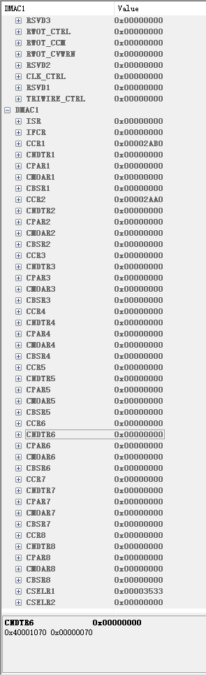
您好,这边用你提供的bin文件烧录后,通过工具查看DMA相关寄存器发现和描述并不符合,描述中打开的是通道7和通道8,实际寄存器中只发现通道1和通道2有值,且CPAR和CM0AR都是0,像是没有工作的样子,没有启用SPI DMA。另外尝试将main.c放入\example\hal\spi\src\main.c下编译,出现有报错情况,可以提供实际的复现工程吗
贾进
17
bin下载后,开机,需要按一下power键才进入spi dma模式。
main文件编译,需要开spi2的tx rx DMA。
具体变异错误是什么?
这边编不了你给的main函数。 可以尝试下在spi2_init里面运行两遍rt_spi_configure,就是把这句话跑两遍:“rst = rt_spi_configure(spi_dev_handle, &spi_dev_cfg);”,看看是否还会出现问题
贾进
21
编译不了,是什么错误吗?是不是需要配置SPI2的DMA?
好的,我验证后回复你。